Embedded Whistle Synth |
May 14th, 2024 |
| music, tech, whistling |
To get good quality audio in and out I was using a 2i2 audio interface, which is expensive, bulky, and has a lot of buttons and knobs that can be bumped.
To use a single mic for both whistle and talkbox I was using a cheap passive A/B switcher. Which feels fragile, causes pops when phantom power is on, and is one more thing to plug in.
It's hard to get super low levels of latency with the Pi. It's probably possible to get more performance out of my existing hardware than I'm managing, but as it is I'm not happy with it.
The Pi's SD card gets corrupted every so often, so I carry around a bunch of spares.
The Pi takes a little while to boot, which makes "no sound" ambiguous between "because the SD card is corrupt or I've plugged something in wrong" and "because it's still starting".
After my Electronic Harp Non-Mandolin project I was feeling more at home with electronics, and decided to build an embedded version of my whistle synth.
It's built around a Teensy 4.0 with the audio shield. [1] This gives me stereo 44.1kHz in and out, though currently I'm just using mono. It's plenty fast for the processing I'm doing.
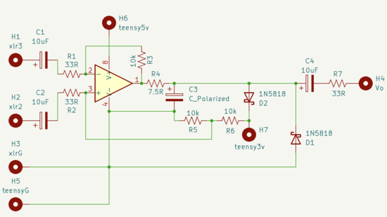
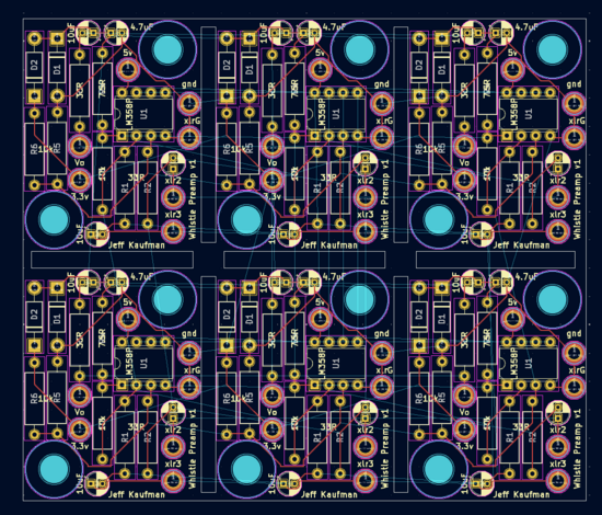
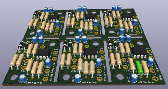
I'm using a standard dynamic mic, which puts out a very weak signal. Instead of connecting that directly to the line in on the Teensy, I need a pre-amp. A normal pre-amp is fancy, but literally all I need here is something that preserves zero crossings and gets amplitude about right, so I made my own around an LM358P (github):
If you want any of these boards let me know; I have dozens of them because the minimum order was five sheets and each sheet has six boards.
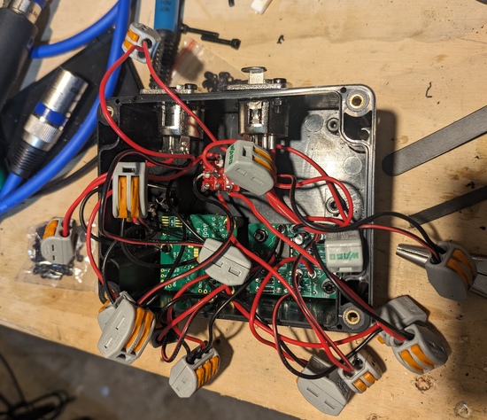
I breadboarded it to make sure it worked, and then mounted the electronics in a project box:
This is an absurd number of lever nuts: once this isn't a prototype anymore I'll take all of them off and solder the connections.
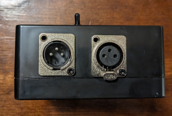
The box has XLR connections for input and output, because it incorporates the A/B switching functionality. With the 3P3T switch on the top I can send the XLR input to the whistle synth, or pass it unmodified to the XLR output.
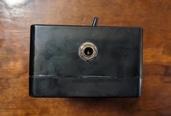
The whistle synth output is 1/4", for use with guitar pedals:
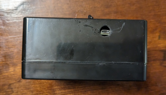
It gets power (and updated programming) over micro USB:
Here's an example of it generating a simple sine wave, transposed down from my whistling:
And here's what it sounds like feeding that sine wave into the SY-1:
I'm quite excited about this, and it's now to a stage where I could play it at a gig, but there are still a bunch of things I'd like to add:
It really needs a knob for the gate. Sufficiently low levels of audio should be ignored, and how much is enough to start triggering a whistle depends on how noisy the current environment is. Right now I've put something in software, but I need to be able to change it on the fly.
It would be nice to have knobs to control how much of each harmonic to include, especially if I'm going to play it on its own without the SY-1 (which essentially doesn't care, since it's tracking the fundamental).
Another thing that would be nice for stand-alone playing is XLR output. I should be able to do this in software, using the stereo outputs and reversing the polarity of one. If I do this I need to worry about phantom power, but I think putting some capacitors on the output would do it. I'm not sure on the sizing, but if the input impedance of the board is 600Ω then I think I'd need at least 13µF to not lose any audible bass? [2] That's a big capacitor if I need to use a mylar film one, which I think I do because electrolytics want to be polarized and when there's no phantom the output will be oscillating around zero. Perhaps just using a balun would be better.
Another place where capacitors would be good is on the output XLR, so I don't get crackles when switching outputs with phantom. There I don't need to go any lower than a talkbox, so I could use a smaller capacitor.
Little lights to show status (power, signal in, signal out) would be nice for debugging and peace of mind.
A lot more work to do! But for now I'm very happy with it, and am planning to use it this Thursday at the Scout House.
[1] I initially tried using an ADC pin for input and a HiLetgo PCM5102 I2S
DAC for output, because I didn't notice there was a standard
Teensy audio shield. After some frustration around no
audio output I got it working, but then I ran into issues getting
it to work well with the audio library and switched to doing the
normal thing.
[2] fc = 1 / (2 * pi * C * R). So 1 /
(2 * pi * 13.3e-6 * 600) = 20Hz
Comment via: facebook, lesswrong, mastodon
